TR8 Efi Lucas/Bosch System L-Jetronic – Efi – How it Works
The EFi (Electronic Fuel injection) system for the TR8 is actually the well known Bosch L-jetronic system adapted by Lucas. Most components are manufactured by Bosch itself (As you can see by the Bosch part numbers on most of the injection parts). This page aims to give an introduction to the Bosch/Lucas L-jetronics system as used on the TR8.
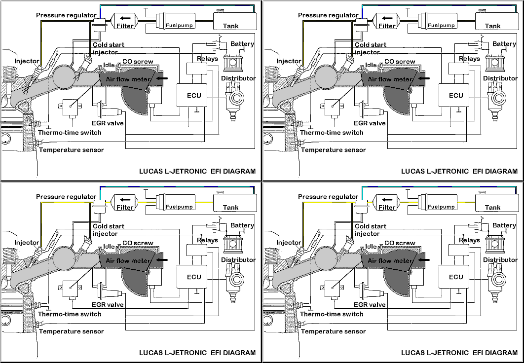
Fuel is drawn from the tank to a highpressure pump which pushes it through a fine meshed filter to the fuelpressure regulator. The excess fuel is drained back into the tank. The fuelis then transported through a fuel rail to the injectors and the cold startinjector. The air is drawn in from the air filter through the air flowsensor which incorporates a temperature sensor. From there the air flowsthrough the plenum chamber into the engine. The injectors are opened for ashort time.
The duration is calculated by the ECUand depends on:
•Air flow measured by the air flowsensor
•Air temperature
•Engine temperature
•Position of throttle butterfly
TheFuel Tank
The tank is standard as on a carburetted car, however it is veryimportant to avoid tank vacuum as the fuel pump is very strong and cansuck the tank inwards!
The Fuel Pump
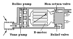
The fuel pump isoperated by an electric motor which is cooled by the fuel itself. Noneed to worry about the pump bursting into flames as the pump nevercontains an ignitable mixture. The pump has two stages. A low pressurevane type pump which is able to suck in the fuel even after the tank isempty. And a high pressure roller type pump which is not capable oftransporting air and therefore relies on the vane pump to prime it afteran empty tank . To prevent too high a fuel pressure there is a reliefvalve incorporated which also guarantees fuel flow when there is littlerequirement for fuel from the engine. (The pump needs to be cooled evenwhen the engine is idling).
The Fuel Filter
The filter is a 2micron filter to prevent foreign particles damaging the injectors or the internals of the engine. It should be replaced every 40,000 miles. On the TR8 it is mounted on the chassis forward of the fuel tank. An arrow on the filter shows the direction of the flow.
Fuel Pressure Regulator
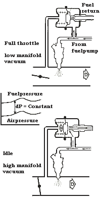
The amount of fuel delivered depends on two parameters: Opening time of the injectors and the fuel pressure. To ensure that the required amount of fuel is injected depends on the opening time of the injectors it is very important the fuel is delivered at a constant pressure difference with the manifold pressure.
When the fuel pressure is low the spring holds the valve against the fuel return pipe and no fuel flows back to the tank. Under low manifold depressions – full throttle, there is a stronger need for fuel from the engine so no fuel will drain back into the tank. This is important because with high manifold pressures fuel is sucked in more easily from the nozzle. To ensure an equal amount of fuel is injected the fuel pressure therefore needs to be reduced depending on the manifold pressure.
When the manifold pressure is high- idling or overrun – the diaphragm valve is drawn against the spring and fuel is drained back into the tank. Fuel pressure drops consequently and prevents to much fuel being sucked in.
Injectors
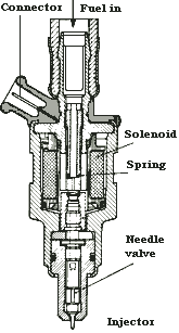
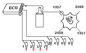
There are eight of these on your TR8. The injectors are needle valves which are opened by the electrical solenoid. When current flows through the coil the valve opens against the spring pressure. The duration time for which the injector is open is determined by the ECU. The injectors don’t operate one after the other, they are switched in two banks. The injectors on the right cylinder bank are numbered 1, 3, 5, 7 The left bank accordingly 2, 4, 6, 8. All injectors of one bank inject simultaneously. When loosening the connectors on these parts, be careful because the connectors tend to become very brittle with age.
Resistors
The resistors areconnected in series with every injector and reduce the 12V Voltage to3V, measured over the injectors when they are energised.
Cold Start Injector
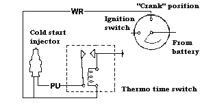
This injector is located in the top of the plenum chamber. As its name indicates it injects additional fuel when the engine is cold and the engine is being cranked. The cold start injector injects continuously and not intermittently like the other injectors. The injector gets its signal directly from the Thermo Time Switch and is not switched or controlled by the ECU.
Thermo Time Switch
The thermo time switch controls the operation of the cold start injector. It is basically a pair of contact points, one of which is mounted on a bi-metal strip. A heater coil is fitted around the strip. The system works when the ignition switch is in the “crank” position. Whenever the bi-metal is cold the points are closed and the injector is operated. During the time the contacts are closed the current is heating up the strip. After max.12 secs (depending on ambient temperature) the bi-metal opens the points and injection stops. When the engine is already hot the bi-metal strip prevents the injector operating during cranking. Notice that the extra air valve uses the same basic principle of a heated bi-metal strip.
Coolant Temperature Sensor
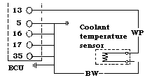
This sensor is located at the front of the inlet manifold in the coolant gallery. It can be mistaken for the Thermotime switch but this one is less bulkier. It gives a signal to the ECU about the engine temperature so that the ECU can inject more or less fuel depending on engine temperature. It does not affect the cold start injector!
Extra Air Valve
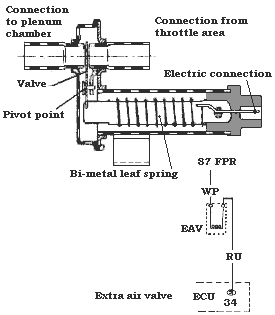
The Extra Air valve allows additional air to by pass the Throttle butterfly. This gives the engine a somewhat higher rpm on idle when the engine is cold. This prevents the engine from stalling. When the fuel pump is running, current is passing through a heating coil in the valve. The bi-metal spring is heated and slowly closes the valve. Once the valve has closed the heat generated by the engine itself will ensure it does not open again until the engine has cooled down. On worn engines this valve can sometimes stick because of oil residues, resulting in difficult starting because the engine won’t idle properly. The coil is connected to terminal 87 of the fuel pump relay and earthed at pin 34 of the ECU.
Idle Screw
This screw controls a throttle valve by pass. By passing more air around the throttle butterfly the engines rpm increase when idling. It can be set with a screwdriver and changing the setting does not have any effect on CO
Potentiometer
The position of the throttlebutterfly and its rate of movement is detected by a potentiometerconnected to the pivot axis of the butterfly. The potentiometer thengives a signal to the ECU. The position of the potentiometer isadjustable. To set it properly:
•ignition on
•connect the Voltmeter(setting on 10V!! not any higher) between the red and green leads
•Reading should be 325 +/-35 mV
•If incorrect slacken thetwo screws and turn potentiometer
•tighten screws and recheckvoltmeter
Air Flow Meter
The air flow meter together with the ECU is one of the most important parts of the injection system and should not be tampered with – most TR8’s have the adjustment screw disabled either by a cover, or in later meters no screw at all. This is to prevent adjustment of CO and so it conforms to the various US/CAN emission laws.
Electronic Control Unit (ECU)
The brains of the system all the data from the sensors and the airflow meter are fed into this silver box (located under the glove box in a grey plastic cover); it then computes how long and how fast the injectors have to do their work and carries out the appropriate actions.
Distributor
The distributor sends a signal to the ECU. From this signal the ECU knows the engine speed and is able to calculate when the injectors must inject. Being an8 cyl. engine the ignition reluctor inside the distributor has off course eight ‘points’. Only four are used to signal inject. Remember that the injectors are switched on/off simultaneously in two banks, so for every revolution of the distributor every injector injects two-times. Because the distributor turns at half the speed of the engine this means that every injector injects once per revolution of the crank.
Battery
Unless you have a diesel engine it won’t go without electrics…..and this is even more so if your engine is equipped with injection, so it is very wise to keep this box in very good condition. If the voltage drops the injector current also declines, this means less fuel being injected. To compensate for this the ECU makes sure the total amount of fuel injected is independentof the system voltage. This is done by increasing the duration ofinjection when the Voltage drops.