Please note: it is down to individual TR8 owners to satisfy themselves that what they are about to do is within their ability or the ability of the person carrying out the repair. I accept no responsibility whatsoever with regard to any repairs you may make or parts you may fit as a result of the information placed here. It is my personal belief that the information given here is 100% correct. A number of people have contributed to this information over the years but in the main this is with great thanks to Gene Thompson.
ECU Update
Here are a few notes about the TR8/SD1 fuel injection system:
The ECU operates in “open loop” mode – ignoring the lambda sensors – until the engine coolant sensor reaches about 30° C. The lambda sensor circuit modifys the air/fuel ratio by changing the intake air temperature signal, causing the ECU to think that the incoming air is more or less dense than it actually is.
Many non-US SD1s and Range Rovers (until ’89) use a version of the the 4CU ECU with the lambda circuit components removed from the lambda circuit board. Additionally, they use an additional circuit to enrich the mixture at throttle openings greater than 75%. The US 4CU includes all the required components except one – R901. Putting a 220K resistor in for R901 should give extra enrichment at full throttle. I don’t know if it will help stock engine performance or not, but as far as I can tell, late ’81 US cars used the exact same FI system and claimed a few more horsepower. The only difference seems to be richer operation caused by increasing the fuel pressure by 7 PSI.
Unlike many fuel injection systems, the 4CU stays in closed loop mode even at wide open throttle. If missing component D803 is added, the ECU will switch to open loop operation at full throttle.
The enrichment signal developed on the lambda board is labeled “lambda out” on the schematic. In closed loop mode it is pulled toward Vcc by R909, R910 and R911 and pulled toward ground by the open collector output of U901C through R908. The lambda sensors contribute their opinion through R825 or R828. In open loop mode, the enrichment signal is pulled closer to Vcc by R907 and R908 in parallel with R909, R910 and R911. Judicious adjustment of the resistors can tailor the response as needed.
The accelerator pump circuit is largely separate from the main control logic. It reads several signals, does some digital and analog stuff and controls the injector drivers in parallel with the main control circuit. Replacing missing components D903 and R912 should result in more agressive accelerator pump action. I don’t know what the best value for R912 is. The throttle position sensor also provides an enrichment signal to U101 through the part of the circuit connected to “PAD_A”.
To ease troubleshooting and adjustment, the ECU can be forced to operate open loop by grounding pin 19 of the wiring harness connector – In a Jaguar 6CU ECU, this is used to put the system in open loop mode when the automatic transmission is in Park or Neutral because the lambda sensors cool down enough while idling to stop working properly. Although the contact is missing from the TR8 connector, position 20 does have an unused contact attached to a blue/purple wire. After cutting that wire at its little three wire splice “stub” just inside the firewall grommet, a little careful work with a paper clip will release the contact inside the connector and allow it to be moved to position 19. Do not ground the wire to the ECU case, because there is a thousand ohm resistor between the case and chassis ground. You can add a switch that will put the ECU into and out of closed loop mode for tune ups, etc.
I haven’t tried any of this myself. In the USA, the EPA says off-road use only, so do it at your own risk.
The graph “U102_output.gif” shows what the analog-to-digital converter chip does. It reads the air flow meter and tachometer signals and derives a 7 bit number that represents engine load. It basically acts as a “virtual vacuum gauge”. Coasting downhill with a closed throttle outputs a low load number (high RPM with little air flow), while wide open acceleration causes higher air flow at lower RPM and outputs a high load number.
Many EFI systems measure manifold vacuum directly, using a manifold absolute pressure (MAP) sensor. The Jaguar V12 version of the 4CU ECU is called the 6CU and uses a MAP sensor instead of an air flow meter. The unusual layout of the V12 would have required two air flow meters or one very large one with difficult to package intake plumbing. There is also less flow restriction without the flap type air flow meter. On the other hand, engine wear, performance modifications or even dirty air filters will throw off the calibration of a MAP sensor equipped system.
The block diagram shows my best guess about what goes on inside the two custom ICs in the ECU. It is based on a diagram released by Lucas describing the P-Digital system as used in the V12 Jag XJS.
Lambda board and schematic
Lambda board and schematic
Block diagram
Coolant sensor
Q305
Q401
Q502
U102 output
My thanks to Gene Thompson for the above update
TR8 ECU
The TR8 ECU is a sealed unit and should where possible be repaired professionally how ever as that’s not always possible 40 or more years on, this section attempts to give some pointers on how to go about fixing the problem.
How do you decide if your TR8 has a bad ECU? Here is a short list of symptoms:
SYMPTOMS:
(1) car abruptly dies or won’t start,
Symptom (1), although similar to what happens when the electronic ignition amplifier or coil dies, is caused by loss of power inside the ECU
(2) car intermittently loses power,
Symptom (2) is caused by a loss of switching current on one bank of injectors.
(3) car surges under part throttle or idle, warm or cold engine.
Symptom (3) is caused by bad feedback loop(s) in the oxygen sensor circuitry.
Any one of these symptoms may indicate a bad ECU. However, before assuming the worst, you should first do a cursory check of the other parts of the injection system. If a process of elimination points to a bad ECU, the easiest test you can perform to check your suspect ECU is to take it to a working FI car and plug it in. [N.B. It’s always good practice to disconnect the battery before unplugging or plugging in an ECU.] Do not, by the way, take a working ECU and plug it into your nonworking car. You could damage a good ECU (and a friendship) that way!
REMOVAL and DISASSEMBLY:
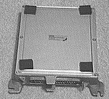
Let’s assume you’ve decided that you may indeed have a bad ECU. If you haven’t already located it, you can find the ECU underneath the glovebox, hidden by a grey plastic cover on the passenger side of the car. After you’ve got the ECU out of the car (and determined it really is bad), take it to a clean workplace with good light. You’ll need to do some resoldering so have a small (25 Watt) soldering iron and some rosin core solder handy. Unscrew the six long “bolts” (maybe “screws” is a better word) holding the top and bottom cover in place and remove the covers. If your ECU has never been opened before, two of the corner screws will have little metal caps that you’ll have to pry out before you can get to the screw heads. If your ECU has been opened, the metal caps will be missing. With the top off, your ECU should now look like the one below.
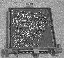
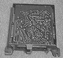
If you remove the two boards from the housing (by removing all the little screws on the edges of the boards), you can actually manoeuvre the boards out of the housing.
Notice the following things: There are three large power transistors on the silver coloured plate at the right hand edge of the right hand board; the top and bottom transistors are responsible for switching each injector bank on and off, the middle transistor has to do with supplying power to the ECU circuitry. The large capacitors (the rectangular box-like things) you can see on both boards are surrounded by some brown goo; the brown goo is glue. The large yellow capacitors at the top of the left hand board play an important role in the O2 feedback circuitry. There are two ribbon cables connecting the two boards. We’ve determined that the right hand board contains all the usual fuel injection circuitry and the left hand board is mostly the O2/lambda feedback circuitry.
So, what causes the ECU go bad? The answer is simple: vibration and bad solder joints. Small electronic parts are often held in place with just the solder joint. This means the solder is performing a mechanical function as well as an electrical one. However, with larger parts like the power transistors and bigger capacitors, a mechanical solder joint will quickly fail in a vibration-prone environment like a car. That’s why the power transistors are screwed in place and the large capacitors are all glued down. Alas, one of the problems with the TR8 ECU is that the solder joints on the large, glued-on capacitors fail anyway. The solder joints on the power transistors are even more likely to fail. The rapid switching of the injectors causes repeated heating and cooling of the solder joints which, in turn, causes them to become brittle. Brittle joints will crack much easier than new ones, sometimes even with just wee small vibrations. Once the joint cracks, the area inside the crack oxidizes. The layer of oxidation doesn’t conduct well and eventually the joint fails electrically.
FIXING THE ECU
For symptoms (1) and (2) [injectors not firing] the solution is just to resolder the solder joints connected to the power transistors (you’ll have to turn the board over to see the joints). Add some new solder to the joint and make sure to heat the joint until the solder flows. (A clean soldering iron with a freshly “tinned” tip is important for this kind of work).
For symptom (2) the joints which connect the transistors to ground seem (in our experience) to be the most likely to be bad. However, it can’t hurt to “reflow” the other joints while you’ve got everything apart. It also won’t hurt to add more solder and reflow the joints where the traces connect to the pin connector (which, in turn, connects to the wiring harness).
For symptom (3) [surging], you’ve got a little more work to do. The solder joints for the two largest yellow capacitors at the top of the left hand board are the most likely culprits. However, for good measure just resolder the leads on all the large capacitors which are glued onto the board. These are the solder joints most susceptible to vibration damage. So that’s it. If you don’t feel comfortable doing this kind of work, find someone in your local club who’s adept with a soldering iron and show her (or him) this article.
WARNING:
One final note. Bob Rowley of EightParts in Tucson, AZ reports that some ECU’s have been damaged by charging or jump starting the battery using one of the “Quick Charge” settings found on commercial battery chargers. It’s suspected that these chargers burn out the ECU because they charge at a higher voltage. It may be possible to repair these ECU’s but not with the simple fix we’ve outlined above. Simply jump starting the car has also caused a few ECU failures. Moral: keep your battery in tip top shape!
Please note: it is down to individual TR8 owners to satisfy themselves that what they are about to do is within their ability or the ability of the person carrying out the repair. I accept no responsibility whatsoever with regard to any repairs you may make or parts you may fit as a result of the information placed here. It is my personal belief that the information given here is 100% correct.